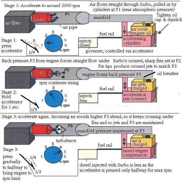
Diagram below shows the air pressure accumulation within the Surbo system as the Surbo is activated through Stages 1 to 3.

where P1 is the initial inlet absolute air pressure, P2 is the Surbo's pressure setting, and P3 is the back pressure formed by the temporarily decreased acceleration.
| Stages/ {Surbo System Component} | {Surbo (red), presses air into grey pipe} | {Oil chamber, in orange} | {Governer, controlled by accelerator, in white box} | {Intake manifold, in light grey} | {Engine, bottom block in pink} | {Exhaust, not shown} |
| initial acceleration (Stage 1) | air flows straight through | is pressed to inject diesel for acceleration | normal absolute pressure | is sole energy source | ||
| pressure accumulation (Stage 2) | begins to cross-jet and form vortex internally | fills up with engine back pressure | is held still for 1 second to reduce engine acceleration, to generate a back pressure towards the Surbo | fills up with engine back pressure | cylinder pressure increases due to lessened acceleration but air still rushing in | exhaust back pressure increases, ready to blast air out |
| vortex (Stage 3) | Surbo spins air within itself, drawing more air in | acts as air pressure accumulator | is pressed slightly more and varied slightly around half way point | half accelerator pressure means half as much diesel injected | higher cylinder compression because of moderately increased air pressure | blasts air out instantly because exhaust already under full back pressure |
| scavenging: pulling gases through (Stage 3 and afterwards) | Surbos's internal vortex suction pulls air in harder than before | half accelerator pressure prevents over-fueling and smoke | higher air density imparts more force to air to overcome flow friction losses | abundance of air to completely burn the diesel injected | higher mass flow to push through exhaust or turbocharger along it |
Read the similar study for petrol vehicles.
Related pages:


